As published In “Modern Machine Shop Magazine”
“The Process with Today’s Tooling Options”
About the Author Bradley R. Teets - Manager of Engineering
Bradley Teets received his bachelor’s degree with honors in 1977 from Fairmont State College and did post graduate work in mathematics and physics at the University of Akron. He worked five years at Manchester Tools as senior design engineer. Since then he has worked for Iscar Metals; duties included project manager, regional sales manager, plant manager, and chief technical officer. He has traveled the USA, Europe, Japan, Middle East and China concentrating on grooving, threading, and cutoff tooling. Bradley Toots holds several patents on carbide grooving and threading tools, has lectured at National Manufacturing conventions and published a variety of articles in the USA and abroad on advanced cutting tools.
INTRODUCTION
The world has been using threads since the days of Archimedes (278-212 BC) when he cut spiral grooves on a cylinder, lowered it in water, rotated it and water rose. Since then volumes of books on threads have been written covering threads and thread standards. This article provides practical shop tips for single point threading on today’s CNC machines and compares different carbide tool designs. The goal is to get a clearer understanding of the threading process so the user can make an appropriate informed choice.
BACKGROUND
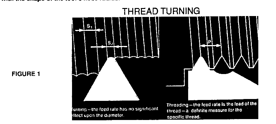
To cut threads on a lathe a tool is fed at a fixed rate past a rotating part. A spiral groove is cut, the shape of which matches the nose of the insert. Threading can be thought of as just a special type of turning with a form tool. Figure 1 shows a turning Insert close up. Notice as the feed rate decreases from S1 to S2 the ridges or grooves come closer together, with no significant effect on the diameter. The part is left with the shape of the tool’s nose radius.
The lateral feed rate in turning is set considering a variety of factors such as; part finish, insert nose radius part rigidity, material being cut, etc. In contrast with threading the lateral feed rate Is not a variable. The feed rate is fixed for each thread pitch. Lateral feed produces the lead and pitch for single start thread.
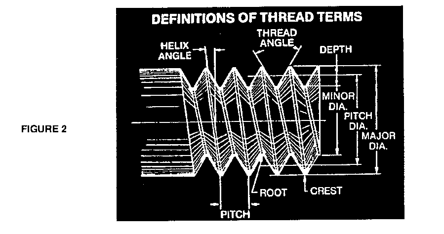
Figure 2 illustrates the basic terms of threading. One of the best sources for details on threads is the “Machinery’s Handbook” which abstracts many thread standards. This article will cover only 60- degree UN series.
THREADING VARIABLES
Threads, like people, are either right or left handed. Most threads are right handed. A bolt with a right hand thread is screwed in by clockwise rotation while looking at the head end. A right hand thread can be cut with either CW (Clock Wise) or CCW (Counter Clock Wise) spindle rotation, and the same is true for left handed threads. it all depends on which direction you start to feed from, toward the headstock or away from It. if you change the direction of feed you change the hand of the thread for a given spindle rotation. To complicate matters further, tool holders are also handed.
The considerations when selecting spindle rotation, direction of feed, and tool holder hand are as follows:
Spindle Rotation:
Machines which normally run CCW (engine lathes, turret lathes, screw machines) often will perform poorly when rotated CW, or do not run CW at all. Machines which normally run CW (CNC slant bed machines) can always run CW and CCW (primarily because the slant bead design puts the cutting forces into the ways when running CW. The CCW ability is so these machines can use commonly available right hand drills, taps, etc.).
Direction of Feed:
Feeding toward the chuck is beat. When the tool first starts to cut there IS a force surge as the tool contacts the work piece. Because of the 60-degree nose form, a lateral push or pull results on the part, and insert. When you feed toward the chuck this force tends to push the part into the chuck. Feeding away from the chuck tends to pull the part out of the chuck. Pulling the part out of the chuck can be hazardous on marginally chucked parts. Given hand of thread, and spindle rotation, there is only one possible choice for direction of feed.
Hand:
The tool holder hand should be such that the lateral feed surge force pushes the Insert Into the holder. For maximum rigidity the part should be chucked close to the spindle. If you select the wrong hand you must over extend the part. if the part has a thread along a shoulder you have only one tool holder choice.
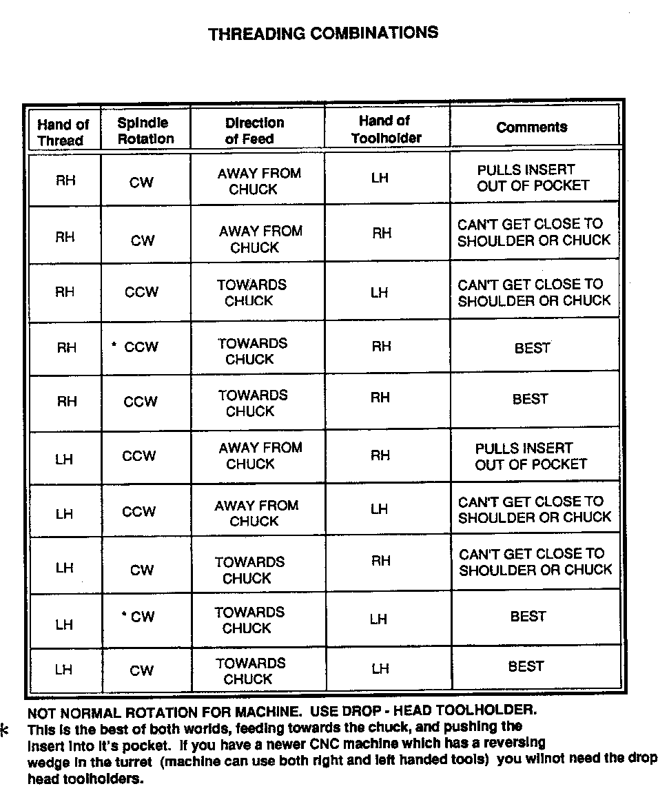
If all this sounds confusing, you are right Luckily there are only eight possible combinations of hand of thread, rotation, direction of feed and tool holder hand. Two other options are included which involve reversing the normal rotation of the machine and using a “drop head” tool holder.
This chart summarizes these options:
APPLICATION VARIABLES
Three methods of in feeding are: RADIAL, FLANK, AND ALTERNATING FLANK.
Radial in feed:
Radial in feeding is the most common method. it’s easy to apply and the best
in feed method if the material is easy to cut, the thread is a 60-degree yes
(UN-SERIES), and the thread is 20 treads per Inch or finer. For difficult
materials or course threads, or non 60-degree V threads, the radial in feed
method is not recommended because there is too much chip engagement. The chip
wraps all the away around the insert. This causes heat to concentrate at the
nose, which lathe weakest part and does the most work.
As shown In Figure 3, the in feed distance should not be constant but the goal is rather to have the cut chip area constant. If the in feed depth was constant then each successive pass would remove a proportionally larger chip area.
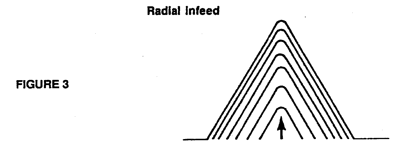
The total in feed depth is approximately 60% of the pitch for UN series threads as expressed in this formula.
IN FEED DEPTH = PITCH x .6
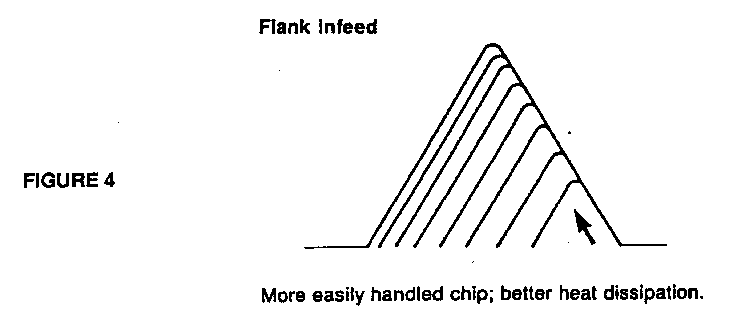
Flank in feed:
Flank in feed (Figure 4) more easily handles the chip and better
dissipates heat. This method can be applied even on older manual lathes by
setting the compound slide to one half the thread angle then in feeding from the
compound elide. Most CNC machines have standard canned cycles” for flank in
feeding. If your machine has this option, use it.
Alternating Flank in feed:
Alternating flank in feed (Figure 5) is best. Alternating flank has all the advantages of flank in feed and additionally, equally distributes the wear on both flanks. This method, however, is rarely used because of cumbersome programming.
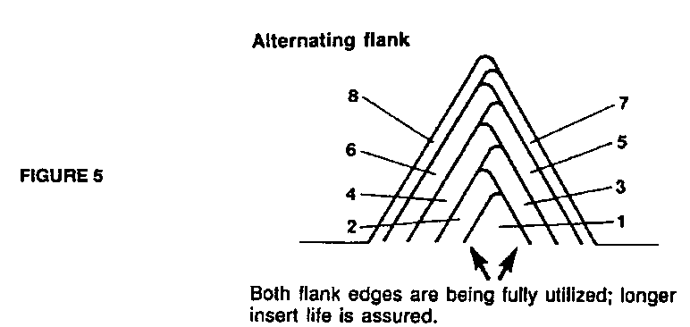
Both flank edges are being fully utilized; longer insert life is assured.
Number of Passes:
To determine the number of passes for most 60-degree threads, use this formulas:
Number of passes = ( 72 x pitch ) + 4
example: thread = 1” - 8
pitch = 1/8 = .125
Number of passes = (72x.125) .4 = 13
NOTE: For harder material, make more passes.
Speed:
The maximum speed (SFM) for threads one Inch and smaller is often determined
by the maximum safe longitudinal feed rate for the machine. RPM and longitudinal
feed rate are linked by the thread pitch. Threading is rarely done at slide
speeds greater then 155 inches par minute. When calculating RPM check the
machine manual If you intend to use a speed which results in a longitudinal feed
greater than 100 inches per minute. If you end the threading pass off the part,
not close to the chuck or shoulder, then higher speeds may be used.
To calculate the longitudinal feed first check the manufacturers recommendation for SFM for that material. Knowing SFM, calculate RPM by the following formula:
RPM = SFM I (.262 x DIAMETER)
Longitudinal Feed:
Knowing RPM and Pitch you can easily calculate longitudinal feed by the following formula:
Longitudinal feed = RPM X PITCH
Single point threading is not recommended on parts smaller than 7/16 because of the machine’s longitudinal feed limitation (usually 100-155 1PM) results in an RPM which fixes the SFM below what is normally acceptable for carbide.
Clearances:
Threading tools must have adequate clearance on both the leading and trailing flank cutting edges. The clearance requirements change with changing Helix angles. Course threads have larger Helix angles for a given nominal diameter. For example, a 1’, -8 has a larger Helix angle than a 1” - 20.
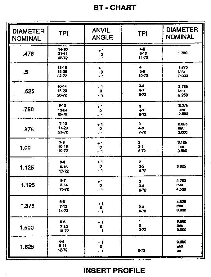
Some threading systems require that you check the Helix angle and change the support anvil. Normally these systems have 1.5 degrees built Into the tool holder. The anvils tilts the insert to the correct orientation for Ideal clearance. There are several ways to determine the Helix angle.
1. Check the Machinist Handbook
2. To estimate use the following shop formula:
Helix angle (approximately) = 20/ (TPI x Diameter)
NOTE: A simple shop formula for approximate tap size is:
DRILL SIZE = NOMINAL SIZE - PITCH
example: 1”- 5 = 1.000 - .125 = .875 diameter
Consult the Machinist Handbook or the thread standard for exact values based on % threads required. The purpose for calculating the helix angle Is to determine the anvil angle. This process can be simplified by consulting the Boundary Transition (BT - Chart). Consult the Machinist Handbook or the thread standard for exact values based on % threads required. NOTE: UNC thru UNEF standard Diameter - Pitch combinations are shown. This chart is for the direction of feed where the feed is INTO the pocket.
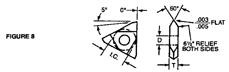
INSERT PROFILE
Partial profile:
Partial profile inserts (Figure 6) are the most common. These Inserts can cut a range of pitches based on the tool’s nose radius. The nose radius of the Insert should be within the root radius tolerance. Carbide vendors often offer two or more nose radius sizes that specifies the limits of pitch. Partial profile designs offer maximum flexibility and minimize tool Inventory.
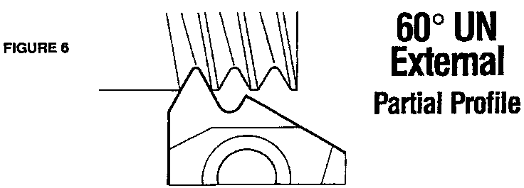
A disadvantage in using partial profile inserts is that the operator must first turn the major diameter (OD thread) to exact size before threading. If the part is a soft steel or made of a ductile material then a secondary operation of deburring after threading may be required.
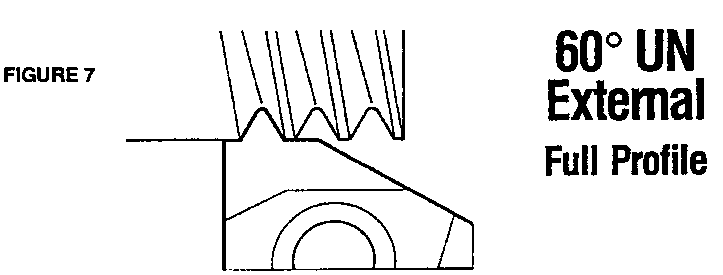
Full Profile:
Full profile (Figure 7)13 the best choice for most applications. Full
profile produces the beat thread form and finish. The leading flank, the root
and the trailing flank are cut simultaneously. The operator need only check
pitch diameter and Is assured that the major, minor and thread form are to size.
This means less work for the operator and less scrap parts. The full profile
option eliminates deburring since it trims the crest removing burrs. The only
disadvantage to full profile Is each pitch requires a separate Insert.
NUMBER OF TEETH
Single Tooth:
A single tooth Is the most common. it offers maximum flexibility, requires a small thread relief, and minimizes tool force. The disadvantages of single tooth vs. multiple tooth are they require more passes, and only one tooth is cutting. (I.. the same nose which rough. out the thread Is expected to make the finish pass.)
Multiple tooth:
Multiple tooth forms are for high production. They are
designed so the form cuts progressively deeper as you go across the insert. The
advantages are 1) reduced number of passes (by a factor equal to the number of
teeth resulting in lower cycle times) 2) only one tooth does the finish cut,
which increases tool life. Multiple tooth inserts are often found in the
automotive and oil industries. Some disadvantages of multiple tooth forms
are 1) each pitch requires a separate insert and different workplace material
may require different inserts for the same pitch since the chip load is
predetermined.
2) a wide thread relief Is required and 3) tool forces are higher.
CARBIDE THREADING DESIGN COMPARISON
There are three basic designs of carbide threading tool in use today.
They are:
1) On - edge triangle
2) Lay - down triangle
3) Grooving system with threading option
On Edge Triangle:
Most carbide vendors supply on - edge triangle designs. The advantages are:
because of standardization the cost to the consumer is low; Insert fits standard
grooving tool holders (is MTVOR/L); tool is simple to use; tool will cut right
or left for threads with a helix angle of +3 to -3; there is a large volume of
carbide supporting the edge; insert has three cutting edges and the same Insert
is used for ID and OD threading. When cutting moderate to easy threads the
on-edge triangle design performs well.
Some disadvantages of the on-edge triangle are: The insert is ground with approximately 7 degrees clearance under the thread form giving it the ability to cut most threads but this requires excessive clearance. This weak cutting edge is asymmetrically loaded and limits insert tool life. Since the insert is on edge it does not enter small holes and can not be used for threads below about 1.5 Inches. Clamping is marginal and it Is time consuming to index. The insert can easily be indexed upside down.
Lay Down Triangle:
Lay down triangle inserts (Figure 9 and 10) are tilted at the helix angle. This allows maximum insert edge strength, equalizes cutting forces and wear, which results in maximum tool life. The lay down profile allows ID threading In small holes down to .550 inches.
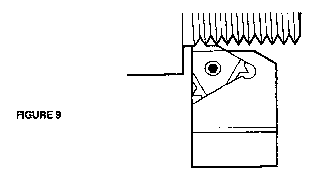
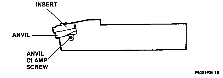
Additionally the insert is very positively clamped by a central screw which does not impede chip flow. Some designs allow indexing of the insert without removal of the screw. Full profile inserts with positive rake are offered as standard.
Some disadvantages of the lay down triangle are tool selection requires checking the helix angle of the thread and sometimes changing the anvil, it can not groove behind a shoulder, the tool holders are normally limited to just threading.
Grooving system with threading option:
Grooving inserts with thread forms ground on them (Figure 11) can reach behind a shoulder or down In a recess. insert fits vendors’ existing grooving tool holder line, and adapts wall to large acme and 60 degree threads. The tool is simple to use and tool will cut right or left for threads with a helix angle of +3 to -3. There Is a large volume of carbide supporting the edge.
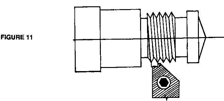
Some disadvantages of the grooving system with threading option are, the insert has only two cutting edges, and if one end is broken off, the other good end may be unusable. The versatilities and trade offs of using 7 degree flank clearance Ike the on-edge triangle design applies. Spare parts, If used, can be quite expensive to buy and replace after a wreck.
Threads have been cut for 2,000 yearn. But in the last 20 years, rapid developments in single point threading tools and CNC machines have made revolutionary progress, in both production rates and tread quality. A clear understanding of single point threading can make your choice the right one.